Quantcast
Channel: Resources for gear lubrication
Viewing all 119 articles
Browse latest View live

Extreme Pressure Additives in Gear Oils

$
0
0

In most slow, highly loaded, geared applications, there exists a lubricating condition that is typical for most failures due to adhesive wear. This condition is known as a boundary condition. In a boundary condition, there is no separation of the interacting surfaces. The function of an extreme pressure (EP) additive is to prevent this adhesive wear and protect the components when the lubricating oil can no longer provide the necessary film thickness.

How It Works
EP additives are polar molecules. Imagine a molecule having a head and a tail. The head of the molecule is attracted to the metal surface, while the tail is compatible with the lubricant carrier (oiliofilic). As the conditions under which metal-to metal interactions become more severe due to higher temperatures and pressures (greater loads), the lubricant film becomes more stressed. The distance between the metal surfaces has decreased to the point where rubbing is occurring and welding (adhesion) becomes highly likely.

Traditional boundary lubrication additives do not remain on the metal surface and cannot prevent the increasing friction, wear and damage to the machinery seen under these conditions. Extreme pressure additives are required in order to enable the specific application operating under these conditions to continue.

There are two main types of EP additives, those that are temperature-dependent, and those that are not. The most common temperature-dependent types include boron, chlorine, phosphorus and sulfur. They are activated by reacting with the metal surface when the temperatures are elevated due to the extreme pressure. The chemical reaction between the additive and metal surface is driven by the heat produced from friction.

Much like when you rub your hands together, as the metal surfaces come in contact with one another, there is heat generated by means of friction and pressure. In reacting with the metal surface, these additive types form new compounds such as iron chlorides, iron phosphides and iron sulfides (dependent upon which compound is used). The metal salts produce a chemical (soap-like) film that acts as a barrier to reduce friction, wear and metal scoring, and eliminate the possibility of welding.

The nontemperature-dependent, overbased sulfonate, operates by a different mechanism. It contains a colloidal carbonate salt dispersed within the sulfonate. During the interaction with iron, the colloidal carbonate forms a film that can act as a barrier between metal surfaces, much like the temperature-dependent; however, it does not need the elevated temperatures to start the reaction.

Basically, EP additives serve as your protection from wear when the lubricant itself can no longer separate the working surfaces. You can now breathe a sigh of relief knowing that you have specified a lubricant with EP where it is needed. Or have you?

Reference
N. Canter. "Additives for Metalworking Fluids." Tribology Data Handbook, edited by E. Richard Booser, p. 862-871. 1997.


Selecting the Right Industrial Gear Oil

$
0
0

It would be great if industrial gears ran in cool, clean and dry environments. However, conditions in gear-driven operations such as steel mills, manufacturing plants and other strenuous industrial applications are anything but cool, clean and dry. That’s why lubricant selection can be so challenging.

Changes Impacting Gear Oil Lubricants
Harsher Environments
Even with regular lubricant maintenance, heat, higher loads and pressures, and contaminants such as water can compromise a gear system. Today’s gear-driven equipment, and the lubricants that protect and allow them to perform well over the long haul, must withstand increasingly harsh environments that also cause quick consumption of essential gear oil additives. This is partly due to the trend toward smaller machines and exposure to diverse applications and punishing operating conditions. In addition, maintenance and plant managers expect higher performance, less downtime and more productivity to decrease costs and improve profits.

Gearbox Size
Today’s gearboxes typically are smaller and made from newer, lighter-weight materials than before. But, these smaller, lighter pieces of equipment are pushed to produce more power and, at the same time, be more durable and reliable than before.

Downsizing gearboxes means less oil and additive to lubricate and protect gears. However, at the same time, equipment loads are increasing. That translates into higher temperatures and more rapid oxidation. Oxidation harms industrial gear oils because it can form sludge that can shorten both oil and gear life. The results are expensive downtime, repair or replacement costs.

Selecting the Right Oil
To handle increased demands, today’s industrial gear oils must contain high-performance additive chemistry. The goal is to keep the lubricant thermally stable and robust enough to ensure that it lasts longer, protects better and performs more efficiently, while at the same time keeping the system clean and carrying away heat and contaminants. This is no easy task. Consider industrial gear oils that at one time were widely acceptable for a given application. Even if these oils meet minimum industry specifications, which can remain unchanged for up to 10 years, they may not be durable enough to protect your equipment.

There are five factors to keep in mind when selecting industrial gear oil that will provide you optimum performance and profitability. Each is discussed in this article.

Fluid Cleanliness
Smaller gearboxes must do the same amount of work as, or even more than, their larger predecessors. But spaces are smaller and tolerances are tighter. That translates to higher speeds and loads. The trend toward smaller reservoirs means the system must cycle the fluid more often with less time to dissipate heat, release foam, settle out contaminants and demulsify water.

Constant gear rolling and sliding produces friction and heat. The heavier operating loads common in today’s industrial settings increase metal-to-metal contact or boundary lubrication, producing even more heat and pressure. To meet longer drain intervals for environmental and cost reasons, the fluid stays in the system longer. Therefore, fluid cleanliness and performance retention becomes critical.

Highly viscous lubricants generate heat from internal fluid friction and also may consume more power to turn the gears. The rate of oxidation in the fluid can increase, which decreases the fluid’s effectiveness and life. In addition, higher operating temperatures increase sludge and varnish formation, which can damage equipment by forming deposits that can block filters, oil passageways and valves. On the other hand, less viscous lubricants generate less heat, minimizing the chance of exceeding recommended operating temperatures or damaging equipment.

Lubricants play a critical role in removing contaminants such as dirt, water, wear particles and other foreign matter that can damage gears and bearings and impact efficient, smooth running of the gears. As the lubricant travels through the filter system, contaminants, which can originate outside the system or from wear inside, should be removed. Even other lubricating fluids that find their way into the system can cause contamination if they are incompatible, thereby reducing performance.

Because they don’t move easily through the filtration system, highly viscous lubricants can be difficult to filter. Pressure at the filter can increase and, if sufficiently high, will trigger a system bypass, allowing contaminant-laden lubricant to circumvent the filters. Equipment damage can follow. Worn gears and higher levels of iron in the lubricant are signs of an ineffective filtration system.

Less viscous lubricants can flow more easily through the filtration system. Contaminants are effectively removed, reducing the likelihood of gear and bearing damage, and increasing equipment life. Another benefit is that the lubricant may need to be changed less frequently, resulting in less downtime and cost.

Fluid Durability
Industrial gear oils must be durable enough to withstand in-service conditions and to retain that performance over time. Although many fluids may meet the industry specification when new, they rapidly lose performance while in service. Industrial gear oils formulated for extended durability will keep gears operating properly and protect equipment investment by extending life, reducing downtime, maximizing productivity and lowering maintenance costs.

Industrial gears often operate under heavy loads and require extreme-pressure protection for gear components. Typical industrial gear oils do not always provide high extreme-pressure performance at low-viscosity greases. This challenges the notion that industrial gears performing in harsh environments must have highly viscous lubricants to be adequately protected.

Industrial
Figure 1. Industrial Gear Oil Trends

Fluid Demulsibility
It would seem easy enough to keep a gearbox dry, but water can creep into the system, particularly the reservoir, in a variety of ways. Mist from water used in routine plant maintenance can enter the reservoir breather, forming condensation in the reservoir after hot-running equipment cools after shutdown. Or, water may enter in some other way. In any case, it can lead to corrosion and decrease performance.

It is vital for the gear oil to be formulated to quickly separate water at both the high and the low temperatures found in industrial gearboxes. The ability to rapidly drain water from the system helps extend the life of both the component and the oil.

Universal vs. Dedicated Fluids
There are two types of industrial gear lubricants. The first, so-called universal gear oils, are formulated so they may also be used in automotive gear applications. Universal fluids may contain components that are both unnecessary for and harmful to industrial gear performance. Or, they may not contain components that are necessary in industrial applications. For example, water separation is not necessary in automotive gear oil applications. However, water separation is critical in industrial gear oil applications; therefore, demulsibility additives must be incorporated.

The second type of gear oil lubricant is called a dedicated fluid. These fluids are tailored for industrial applications by carefully formulating the lubricant with additive components specifically designed for such applications.

The Right Additives
Additives used to enhance extreme-pressure properties in gear oil can be prone to thermal instability, resulting in sludge formation. However, technology is available that provides the optimum balance of thermal stability for sludge-free gearboxes and also extreme-pressure protection for heavy-duty durability.

The combination prolongs gearbox life, maximizes efficiency and eliminates downtime. But most important, high extreme-pressure performance and cleanliness are maintained across a full spectrum of viscosity grades, down to ISO VG 68. Using a lower-viscosity grade can improve efficiency while maintaining durability for optimum performance.

In industrial settings, equipment downtime significantly impacts the bottom line. A lower-viscosity lubricant with optimized additive technology effectively protects gear-driven equipment and ensures its operation at maximum performance.

About the Author:
Tim Cooper is The Lubrizol Corporation’s industrial additives product manager for Europe, Africa and the Middle East. He is responsible for the industrial additives product line, which encompasses hydraulic, turbine, industrial gear and grease additives. Tim has worked at Lubrizol for 23 years in a variety of technical and commercial positions in both the United Kingdom and the United States. These roles have covered a broad spectrum of activities including additives for industrial lubricants, paints and coatings, specialty monomers and surfactants. He earned an honor’s degree in applied chemistry from Trent Polytechnic in 1985. For more information, visit www.lubrizol.com.

How Not to Lubricate a Gearbox

$
0
0

The vibration data acquired on a small helical gearbox with three shafts supported by tapered roller bearings indicated symptoms consistent with impending bearing failure. The vibration pattern that helped to identify the problem as lubrication-related is discussed in this article.

Fault Frequencies

Both inner and outer race bearing faults were present in the spectrum (Figures 1 and 2). Random impacting of high magnitude was indicated in the time waveform (not shown). An alarm showed that lower-order harmonics dominated the spectrum, and their magnitudes suggested bearing fault in an advanced stage.

Inner
Figure 1. Harmonics of inner race bearing defect frequency M=BPFI.

Outer
Figure 2. Harmonics of outer race bearing defect frequency L=BPFO.

Bearing
Figure 3. Noise modulating by bearing cage frequency J=FTF.

The modulation of a random signal by the cage frequency was also observed in the PeakVue data (Figure 3). It has been theorized that due to dry operation, both the inner and outer races wore out to a point that the round geometry of the races had been compromised. In addition, insufficient lubrication caused increased friction between the rollers and the cage. Because of being subjected to modulation by the cage, friction became apparent in the PeakVue data.

After removing the gearbox from operation and disassembling it, the entire space in the gearbox filled with grease, used mainly in open gears, but the lubricant was completely washed out from the bearing areas (Figure 4).

Grease
Figure 4. Grease has been washed out from the bearing areas. Bearing outer races are unevenly worn out.

Results of Metal Wear

The diagnosis was confirmed by observing the damage sustained by the input shaft bearing. Extensive wear was present in the outer race (Figure 5). A rough surface was not the only result of the metal wear. A groove up to 0.015-inch deep also developed in the path of the rollers.

Groove
Figure 5. A groove up to 0.015-inch deep is present in the outer race.

The inner race exhibited a similar pattern (Figure 6). No pitting or spalling was observed on the surface. The cage was also excessively worn out and broke off in several locations. This, along with the smaller inner-race diameter, compromised the separation of the rollers (Figure 7).

Worn
Figure 6. Worn surface on the inner race. A groove developed in the path of the rollers.

Cage
Figure 7. Cage is damaged. No lubricant is present.

An observant reader may ask why grease was used in a gearbox instead of oil. Consider this wintertime scenario: In attempting to warm up the room, you turn up the thermostat instead of shutting the door to retain the heat. Dealing with a symptom instead of the root cause is still a common approach to solving problems.

In this case, the lubrication scheme was designed as an oil splash-type, but over time, the shaft seal started to leak. To prevent oil from escaping, lubricant flow properties have been adjusted for the leaking seal by draining the oil and filling the entire space of the gearbox with grease.

While there was some grease still left in the bearing area, it operated almost satisfactorily, possibly slightly hotter, than normal. But once the initial charge was depleted, the lubricant could not be delivered, even with the excess grease in the gear casing. The same is true for the lubrication of the gears.

Making lubrication modifications without considering the lubrication scheme could be detrimental to you and your equipment.


About the author:

David Gluzman is a Certified Reliability Engineer (CRE) with Temple-Inland Corporation, a manufacturing company focused on corrugated packaging and building products. Gluzman also holds Machine Lubrication Technician Level I and Level II certifications through the International Council for Machinery Lubrication.

Applying Open Gear Lubricants

$
0
0

When selecting an open gear lubricant for use in a particular application, the method of application used must be considered. The typical methods of application used in open gear systems are:

  • Spray/atomization systems

  • Gravity feed or drip feed

  • Oil bath (splash and idler immersion systems)

  • Hand, brush or pour it on

Generally, if the open gear lubricant is to be applied by a drip system, force-feed lubricator or spray system, it must be sufficiently fluid to flow through the application equipment. For brush applications, the open gear lubricant must be fluid enough to be brushed evenly on the teeth. In any case, during operation, the open gear lubricant must be viscous and tacky enough to resist squeeze-out from the gear teeth. When open gears are lubricated by dripping into a splash pan or through the use of splash and idler immersion systems, the open gear lubricant must not be so heavy that it channels as the gear teeth dip into it. Finally, when open gears are lubricated, the consistency or grade and its ease of pumpability must permit easy application under the prevailing ambient conditions.

Spray/Atomization Systems
The most common type of spray/atomization system used in the lubrication of open gearing is the intermittent mechanical spray system. Its usage depends upon the open gear lubricant remaining on the gear teeth through several revolutions. Intermittent spray systems utilize metering valves that direct the lubricant to an air/grease nozzle that sprays the lubricant onto the open gears with the assist of air pressure. The basic components of this type of system are a pump, a controller, a metering valve, a spray manifold and spray nozzles.

The operation of this type of system is very straightforward. A signal from a controller turns on the pump to supply the open gear lubricant to a positive-displacement metering valve. The metering valve can be a progressive, two-line or injector type. The metered lubricant is sent down a passage in a spray manifold, where the open gear lubricant is directed to a nozzle. A second passage of pressurized air (usually in the range of 80 to 120 pounds per square inch) is directed to the same nozzle. This pressurized air blows the open gear lubricant out of the nozzle onto the open gear. After a predetermined amount of open gear lubricant is dispensed, both the air system and the pump shut off until the next lubrication cycle. Usually there is a delay in shutting off the air so as to ensure that the open gear lubricant has cleared the nozzle. The purpose of this is to remove the open gear lubricant out of the nozzle tip, thus preventing it from drying and clogging the nozzle.

The spraying time should equal the amount of time it takes for one or two revolutions to ensure complete coverage. Periodic inspections must be made to ensure that a sufficient amount of open gear lubricant is being applied to provide proper protection. Two hours is the maximum interval time permitted between applications per the AGMA 9005-D94 guidelines.

The amount of open gear lubricant to use is dependent upon the application the open gear is being used in (mills, kilns, dragline, etc.) and the pitchline velocity of the gearing, the rated electrical power draw on the electric motor powering the gear (for mills and kilns), the type of gearing, and the type of open gear lubricant that is to be applied. In many applications, your lubricant supplier can recommend the starting amount to use. These application rates are expressed in grams per centimeter face width per hour. In lieu of a starting recommendation given by the lubricant supplier, the AGMA has issued lubricant quantity guidelines in the AGMA 9005-D94 standard that can be used for intermittent methods of application.

Lubricant Quantity Guidelines for Intermittent Methods of Application
1) The spraying time should equal the time for one and preferably two revolutions of the gear to insure complete coverage. Periodic inspections should be made to insure that sufficient lubricant is being applied to give proper protection.
2) Two hours is the maximum interval permitted between applications of lubricant. More frequent application of smaller quantities is preferred. However, where diluents are used to tin lubricants for spraying, intervals must be so short as to prevent diluent evaporation.
Table 1. Lubricant Quantity Guidelines for Intermittent Methods of Application (ref. 1)

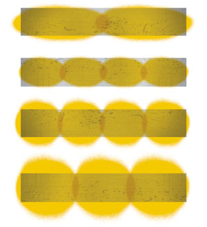
To ensure that a correct amount of open gear lubricant is being applied and operation reliability is being maintained, it is important that you maintain a perfect spray pattern without any gaps. Distribute the open gear lubricant evenly over the entire height and width of the tooth flank on the loaded side of the gear. The number of spray nozzles to use for a given application is determined by the gear width. Typically, four to six spray nozzles are required; they must be properly spaced to provide adequate lubricant coverage across the entire face of the gear teeth.

As a guideline, for slow-speed open gearing operating up to 2,000 feet per minute (10 meters per second), the end nozzles should be placed 2 to 2.5 inches (50 to 65 millimeters) from the gear face edge with the remaining nozzles spaced 5 to 7 inches (130 to 180 millimeters) from center. Nozzle location is also a function of the spray pattern. Spray nozzles are generally positioned to direct the open gear lubricant at the loaded profiles of the gear teeth (not the pinion) at a maximum distance of 6 to 8 inches (150 to 200 millimeters) from the gear teeth.2 The correct spray pattern on the tooth flanks and an illustration of the correct spacing of spray nozzles are illustrated in Figures 1 and 2.

Correct Lubricant Spray Pattern on Gear Tooth Flanks
Figure 1. Correct Lubricant Spray Patterns on Tooth Flanks.
Placement of Spray Nozzles
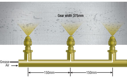
Figure 2. Placement of Spray Nozzles.
Example of three-nozzle spray bar with spray nozzle spaced apart at 150 mm.
Inadequate Lubricant Spray Pattern on the Gear Tooth Flank
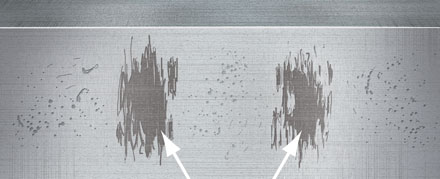
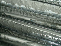
Figure 3. Inadequate Spray Pattern on the Tooth Flank.
Inadequate spray patterns normally lead to scuffing in these highlighted areas. Additional spray nozzles correctly spaced and higher air pressure is required to improve the lubrication film.

The air pressure to the spray bar also must be properly set; otherwise, the open gear lubricant will not be atomized correctly. Too low of air pressure will result in a splattering, lumpy or stringy appearance (as illustrated in Figure 3), while too high of air pressure will tend to blow the open gear lubricant off of the gear. For most open gear lubricants, the air pressure seating must not be set lower than 75 psi (35 kilopascals or 5 bar) and not higher than 90 psi (42 kpa or 6 bar).

Even if the spray nozzles are monitored using control flow mechanisms, periodic checks of the spray pattern are recommended as part of maintaining adequate and even coverage of the open gearing on the gear face. Spray bars have many different designs, and many of the older spray systems do not allow easy access to check the spray pattern while the open gearing is operational. If the spray bar does not swing out or open outward with the door, the safest way to check the spray pattern is when the machine is shut down. A recommended procedure for inspecting spray patterns is as follows:

  1. Ensure isolation procedures are adhered to, then open the inspection door and place a clean piece of cardboard or paper on the gear set, where the spray nozzle atomizes the open gear lubricant onto the gear set.

  2. Operate the lube system and check the lubricant coverage on the cardboard or paper. The coverage should overlap from one spray nozzle to the next, and there should not be any gaps within the appropriate height and width to cover the load-carrying gear teeth.

  3. If gaps are found, the air pressure, spray angle and spray cap need to be adjusted to obtain the appropriate coverage.

  4. Once the adjustments have been made, repeat the process until the perfect spray pattern (as depicted in Figure 1) is achieved.

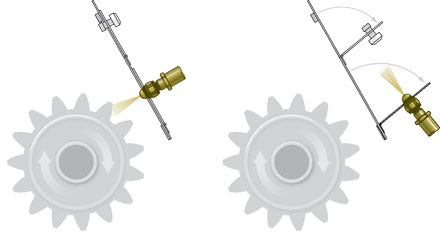
If the spray bar requires changing, the spray bar design should be altered so that spray pattern can be checked during equipment operation (as shown in Figure 4).

Recommended Spray Bar Design
Figure 4. Recommended Spray Bar Design to Allow Easy Checking of Spray Pattern
Spray Bars at Four Directions of Rotation
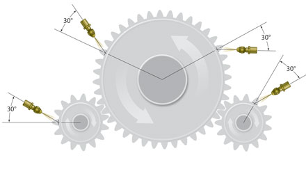
Figure 5. Spray Bars Can be Located at Four Different Directions of Rotation

The spray bar should be set at a 30-degree angle to spray the open gear lubricant onto the drive or loaded side of the pinion or girth gear. Setting the spray angle at 30° (as shown in Figures 5.) will achieve a very good distribution of the lubricant in an upward or downward direction, always to the load-carrying tooth flank. The spray nozzle distance set back from the gear is approximately 8 inches plus or minus 2 inches (200 millimeters plus or minus 50 mm), depending on the air pressure and tooth height. The width of the gear tooth will determine the amount of spray nozzles required to adequately lubricate the gear drive.

To further ensure that the proper amount of lubricant is being applied once the spray bar nozzles and patterns are set, it is recommended that the amount of lubricant being expelled from each injector be weighed. Over time, injector spray nozzles do not deliver the appropriate amount of lubricant per cycle that they are designed to deliver. Too much open gear lubricant being applied can cause waste, while under-lubrication can lead to increased wear and eventual component failure. The amount of lubricant that needs to be expelled from each injector can be obtained from the manufacturer of the automatic lubrication system. For example, a Lincoln SL-1 style injector typically expels 0.046 ounces (1.31 grams) per cycle of lubricant.

The timer settings on the automatic lubrication system should eventually be set to the shortest frequency depending upon the type of open gear lubricant used. For asphaltic and high-viscosity synthetic high-viscosity base fluids, the typical time-setting interval is 10 to 20 minutes, while for semi-fluid greases and gel/polymer-thickened type open gear lubricants, the typical time-setting interval is 15 to 30 minutes.

A strobe light can be used to check the appearance of the gears during operation. The strobe light should be set at the same speed that the gear is turning. A well-lubricated gear will have a dark color to semi-transparent appearance depending upon the type of open gear lubricant being used, and strings of lubricant will appear as the gear and pinion teeth separate. An over-lubricated gear will be black with excess lubricant dripping, flinging off or built up on the teeth and root zones of the gear.

Taking temperature readings across the gear face using a non-contact thermometer can be additionally done to check if the open gearing is being properly lubricated. An even temperature across the gear tooth indicates that the gear is being properly lubricated.

In addition to being used to check for proper lubrication, strobe lighting and temperature reading can be used to check for misalignment. Any misalignment results in less contact across the meshing gears, resulting in increased wear. Roughly a 30 degree Fahrenheit difference across the gear tooth and darker to lighter areas of lubricant across the contact film indicates misalignment.

Gravity-Feed or Drip-Feed Systems
Gravity-feed or drip-feed systems are found on mills, kilns, shovels, draglines and excavators. These systems consist of one or more oilers, cascade pans, pressurized feed lines or applicator wheels. They allow the open lubricant to drip into the gear mesh at a set rate. This method of application is limited to open gearing with pitchline velocities of 1,500 feet per minute (7.5 meters per second) or less.

For these types of systems, asphaltic, high-viscosity synthetic oil open gear lubricants are generally used. If pressured feed lines or applicator wheels are used in these systems, a semi-fluid grease or gel/polymer-thickened type of open gear lubricant can be used.

Oil Bath (Splash and Idler Immersion) System
Oil bath systems are the simplest method of lubricating open gears. The gear or an idler in mesh with the gear is allowed to dip into the open gear lubricant, carrying it around to the mesh. Idler immersion systems are generally limited to open gear systems with pitchline velocities below 300 feet per minute (1.5 meters per second). Some systems will also contain recirculating pumps and filtration systems. Splash and idler immersion system can be found on mill and kiln applications.

As a general recommendation, asphaltic, high-viscosity synthetic oil, semi-fluid grease type and gel/polymer type open gear lubricant can be used in these systems. If a semi-fluid grease type of gel/polymer is used, the open gear lubricant must be semi-fluid to fluid in consistency. If the open gear lubricant is an asphaltic or high-viscosity synthetic base fluid type, the viscosity of the fluid should be a minimum of 1,000 centistokes (cSt) at 40 degrees Celsius.

Hand, Brush or Pour it On
This method of application is one of the oldest and most dangerous methods used to apply open gear lubricants. It has been used to apply open gear lubricants on mills, kilns, shovels, draglines and excavators. Generally, asphaltic type and high-viscosity synthetic type open gear lubricants are applied by this method.

It can result in not only the improper amount of open gear lubricant being applied, but also can result in the introduction of contaminants into the gearing. Further application by this method while the open gearing is operational can result in safety considerations that can result in injury or even death to the person applying the open gear lube.

Lubricating Film Thickness and Selection Criteria
The primary lubrication regime required to lubricate open gearing is elastrohydrodynamic (EHD) lubrication. According to the EHD theory, the critical factor is the open gear lubricant’s film thickness. The open gear lubricant’s film thickness is dependent upon the dynamic viscosity of the open gear lubricant at operating temperatures, average surface velocity of the gear temperature, the loads and geometry of the gearing, etc. It has been established that the lubrication condition which exists in most gears is predominately elastrohydrodynamic. Gear teeth are subject to enormous contact pressures over relatively small areas (possibly as great as 435,000 psi), and yet they are successfully lubricated with very thin films of lubricant. There are two reasons for this:

  • The high pressure causes the surfaces to deform elastically and spread the load over a wider area.

  • The viscosity of the lubricant increases considerably with pressure, thus increasing the lubricant’s load-carrying capacity.

Once the film thickness is determined, another important parameter which must be calculated is the Lambda ratio. This ratio is defined as the ration of EHD film thickness of the lubricant to the composite surface roughness of the contacting metal surfaces. As the Lambda ratio approaches 1 (i.e. the film thickness is of the same order as the surface roughness), it can be expected that there will be increased contact between the two contacting gears.

It should be noted that this calculation is based on the base oil viscosity of the open gear lubricant only. It does not take into account any film thickness contribution that may be made by the open gear lubricant’s thickener system or its solid lubricants. In addition, some types of open gear lubricants – such as grease-like and gel/polymer-thickened types – may contain light-viscosity base fluids. These light-viscosity base fluids are used as a cutback of the heavy-viscosity base fluids present in the formulation in order to enhance the pumpability of the product during low-ambient-temperature conditions. The light-viscosity base fluids are volatile and dissipate under operating conditions. Subsequently, the base viscosity of these open gear lubricants increases, generating a tacky, durable lubricant film that adheres to the gearing.

Properly Lubricated Open Gear
Figure 6. Properly Lubricated Open Gear
Over-Lubricated Open Gear
Figure 7. Over-lubricated Open Gear

Besides taking into consideration the lubricant film thickness provided by the open gear lubricant being selected, other considerations that must be taken into consideration when recommending the proper type, grade and amount to be applied are:

  1. The OEM requirements.

  2. The type of open gear application – mills, kilns, shovels, draglines, etc.

  3. The ambient temperature encountered in the area in which the machine operates.

  4. The climate condition in which the machine operates – ice, snow, wet, dusty.

  5. How the lubricant is being applied.

  6. If applied by a spray or automatic lubrication system, the type of lube system that is installed – Farval, Lincoln, Worner, Droppsa, etc.

  7. The type and ratio of the pump utilized on the automatic lube system.

  8. The width of the pinion gear.

  9. Whether the gearing is a double or single pinion

  10. The power rating on the electric motor.

  11. The position and number of spray nozzles.

Once all of these conditions are known, the proper open gear lubricant for the given application can be selected based upon the different topics, methods of application and characteristics discussed in this paper.

Finally, when switching open gear lubricants or applying open gear lubricants on new equipment where no prior lubricant was used, the following procedures should be followed:

Procedure to follow on new equipment:

  • Clean all coating and debris from the gears.

  • Coat the gear and pinion with a light film of open gear lubricant by some sort of spray method.

Start-up procedure:

  • Run equipment slowly under no load to verify that there is lubricant throughout the entire load zone.

  • Gradually increase speed and load while turning on the automatic lube system.

  • Monitor continuously until a proper coating is maintained.

For spray systems:

  • Prior to startup, purge the lube lines and check spray patterns for complete coverage.

  • Adjust the air pressure and volume as needed.

For drip systems:

  • Most open gear lubricants are designed to adhere where they are applied. Drip tubes should be spaced no farther than 2 inches apart.

Procedure to follow when switching from one type of open gear lube to another:

Although it is best to completely clean the gear, pinion and gear guards, conversion of one type of open gear lubricant to another can be made by applying the open gear lubricant to be used directly over most existing applications.

Procedure:

  • Purge the lube lines thoroughly.

  • Start the timing settings 50 percent higher than the operational settings to ensure all of the lines are purged and flushed and have built up a sufficient lubricant coverage film before reducing the lubricant consumption rate to the operational settings.

  • Readjust the timer to maintain an adequate lubricant film. The lubricant quantity should not be reduced abruptly but at five-minute intervals of 150 to 200 hours for mills and 100 to 150 hours for shovels, draglines and excavators.

  • Product performance should be monitored.

  • When reducing consumption quantity to the control unit of the spray system, it should be set to ensure the intervals between spray cycles are as short as possible. Short and frequent spray cycles ensure the lubricant is supplied evenly to the component; this increases functional reliability.

  • Adjust the air pressure and volume as needed.

  • Inspections of the lubricating systems, tooth flank conditions and the spray pattern are required to ensure reliable operation. The spray system should be maintained thoroughly in accordance with the manufacturer’s instructions.

References

1) ANSI/AGMA 9005-D-94 – “Industrial Gear Lubrication, Table 10”, page 10

2) Ibid, page 11

About the Author

Lawrence G. Ludwig Jr. is the chief chemist/technical director for Schaeffer Manufacturing. To learn more, visit www.schaefferoil.com.

The Ins and Outs of Industrial Gear Sets

$
0
0

A gear is a component within a transmission device that transmits rotational force to another gear or device. Depending on their construction and arrangement, geared devices can transmit forces at different speeds, torques or in a different direction from the power source. The most common situation is for a gear to mesh with another gear, but a gear can mesh with any device having compatible teeth, such as linear moving racks. The most important feature is that gears of unequal sizes (diameters) can be combined to produce a mechanical advantage, so that the rotational speed and torque of the second gear are different than those of the first.

What follows is an explanation of the four most prevalent gearing types/configurations found in an industrial environment. The main purpose of this article is to inform you of a few popular gear types. I made a mistake earlier this month during a seminar and assumed that everyone in the class had an understanding of this topic. It is very hard to understand that different gear types have different lubricant needs if you do not first understand the different types or variations of gear sets.

Spur Gears
Back_Page-Figure1.jpgSpur gears are the simplest and most common type of gear. Their general form is a cylinder or disk with teeth projected radially. In these "straight-cut gears", the leading edges of the teeth are aligned parallel to the axis of rotation. These gears can only mesh correctly if they are fitted to parallel axles. A single spur gear is generally selected to have a ratio range of between 1:1 and 1:6, with a pitch line velocity up to 25 meters per second. The pinion is typically made from a harder material than the wheel. Select a gear pair to have the highest number of teeth consistent with a suitable safety margin in strength and wear.

Helical Gears
Back_Page-Figure2.jpgHelical gears offer a refinement over spur gears. The leading edges of the teeth are not parallel to the axis of rotation, but are set at an angle. Since the gear is curved, this angling causes the tooth shape to be a segment of a helix. The angled teeth engage more gradually than do spur gear teeth. This causes helical gears to run smoother and quieter than spur gears. Helical gears also offer the possibility of using non-parallel shafts.

With parallel helical gears, each pair of teeth first makes contact at a single point at one side of the gear wheel; a moving curve of contact then grows gradually across the tooth face. It may span the entire width of the tooth for a time. Finally, it recedes until the teeth break contact at a single point on the opposite side of the wheel. Thus, force is taken up and released gradually. With spur gears, the situation is quite different. When two teeth meet, they immediately make line contact across their entire width. This causes impact stress and noise. Spur gears make a characteristic whine at high speeds and cannot take as much torque as helical gears because their teeth are receiving impact blows.

Whereas spur gears are used for low-speed applications and those situations where noise control is not a problem, the use of helical gears is indicated when the application involves high speeds, large power transmission or where noise abatement is important. The speed is considered to be high when the pitch line velocity exceeds 5,000 feet per minute.

A disadvantage of helical gears is a resultant thrust along the axis of the gear, which needs to be accommodated by appropriate thrust bearings and a greater degree of sliding friction between the meshing teeth, often addressed with specific additives in the lubricant.

Worm Gears
Back_Page-Figure3.jpgA worm gear is used when a large speed reduction ratio is required between crossed axis shafts which do not intersect. A basic helical gear can be used, but the power which can be transmitted is low. A worm drive consists of a large-diameter worm wheel with a worm screw meshing with teeth on the periphery of the worm wheel. The worm is similar to a screw and the worm wheel is similar to a section of a nut. As the worm is rotated, the worm wheel rotates due to the screw-like action of the worm. The size of the worm gear set is generally based on the center distance between the worm and the worm wheel.

If the worm gears are machined basically as crossed helical gears, the result is a high stress point contact gear. However, the worm wheel is normally cut with a concave (as opposed to a straight) width. This is called a single-envelope worm gear set. If the worm is machined with a concave profile to effectively wrap around the worm wheel, the gear set is called a double-enveloping worm gear set and has the highest power capacity for the size. Single-enveloping gear sets require accurate alignment of the worm wheel to ensure full line tooth contact. Double-enveloping gear sets require accurate alignment of both the worm and the worm wheel to obtain maximum face contact.

Bevel Gears
Back_Page-Figure4.jpgThese are gears cut from conical blanks and connect intersecting shaft axes. The connecting shafts are generally at 90 degrees; and sometimes, one shaft drives a bevel gear which is mounted on a through shaft, resulting in two output shafts. The point of intersection of the shafts is called the apex, and the teeth of the two gears converge at the apex. The design of bevel gears results in thrust forces away from the apex. With the bearing limitations, the gears have to be carefully designed to ensure that they are not thrown out of alignment as they are loaded.

Straight bevel gears are used widely in machine drive systems to effect 90-degree direction changes. They have the same limitations as spur gears and are, therefore, not used on high-duty, high-speed applications.

Accessorizing Gearboxes for Lubrication Excellence

$
0
0

At Clopay Plastics in Augusta, Kentucky, my primary job is planning and scheduling along with being the lubrication leader. My job entails the use of a CMMS software product for assigning work orders for PMs and scheduling shutdowns and other maintenance items for technicians. Gearbox checks were one of the tasks on our scheduled downtime PMs to which maintenance techs did not want to be assigned. Today, they request gearbox checks. What changed? We accessorized our gearboxes!

At Clopay we didn’t just randomly decide to accessorize our gearboxes. In the process of planning the construction of our world-class lube room, we wanted to standardize all the gearboxes in the factory to match disconnects used on transfer carts, storage tanks and top-up containers for the prevention of cross-contamination and particle contamination. Gearboxes were also accessorized for easy oil analysis, and were made user-friendly for topping off and filling and draining, safety and environmental reasons, and retrofitted for offline filtration and identification on all gearboxes.

We purchased a cart with five shelves and stocked it with stainless-steel fittings. Labeled trays were used to sort and organize the different fittings. The cart has casters and it is taken to the machines on scheduled shutdowns for accessorizing gearboxes.


Figure 1. Quick-connect on Gear Box

Standardization of Gearboxes, Storage Tanks and Transfer Carts
A decision was made to use ¾-inch hoses, piping and stainless-steel quick-disconnects on all storage tanks, transfer carts and gearboxes. We used Dyna Equip quick-disconnects because they contain Viton seals and self-contained check valves on both the male and female disconnects. We installed quick-disconnects on any gearbox with a two-gallon reservoir or larger so that the transfer carts can be used for oil drains and fills. For smaller gearboxes, we use Oil Safe® containers for topping off and complete fills.

We fill and drain the oil from the bottom of the gearboxes due to the risk of them becoming pressurized when filling from the top. When filling from the bottom, a gearbox can still become pressurized, but removing the desiccant breather or the ¾-inch plug that is installed for top-offs will release the entrapped air. The ¾-inch plug can be removed so that a quick-disconnect can be installed in the port. This would allow offline filtration with a filter cart to be used while the equipment is still in production. For cost savings, we carry one ¾-inch quick-disconnect on filtration carts that can be installed and removed when completed. We also use adapters to attach the desiccant breather to the top of ¾-inch piping, which can also be removed for top-off or to install a quick-disconnect for offline filtration.

We also installed ¾-inch stainless-steel pipe fittings for draining oil. If a gearbox is two gallons or larger, a quick-disconnect and a stainless-steel locking ball valve are attached. This adds two levels of protection. With only a ball valve, a person or vibration could open the ball valve causing the oil to drain out, starving the gearbox of oil if no one catches the open valve. The quick-disconnect attached has a built-in check valve that will not allow the oil to drain unless a male disconnect is connected, adding the second level of protection. For smaller gearboxes, a drain pipe is also attached, but without quick-disconnects because these small gearboxes are filled with oil-safe containers. A locking stainless-steel ball valve is installed to reduce the chances of the valve being accidentally opened.


Figure 2. Sight glass added with oil sample
port combo, desiccant with stainless piping
and top-off plug between gearbox and
desiccant.


Figure 3. Waste Oil and Filter Carts

Safety and Environmental
Radiator-style hose clamps will never be observed in our facility. These have been outlawed in all of Clopay factories due to maintenance personnel and operators being cut by the sharp edges on the clamps. We have standardized gearboxes, lube room equipment, storage tanks and hydraulic reservoirs with a ¾-inch push-on multipurpose hose with a push-on stainless-steel barb hose end. When pushed all the way onto the adaptor, the hose seats into the blue finishing cap. One must be careful when selecting hoses and push-on adaptors. Check them for compatibility with the oil, pressure ratings and temperature ratings.

On many gearboxes before the drain pipe extensions were added, the oil was normally drained out onto the floor or onto the mounting platform. Floor dry or absorbing material was then used to clean up spills. With drain extensions, a waste cart can be used with quick-disconnects or on smaller gearboxes so the oil can drain into what we call popcorn buckets (officially termed lilly pops). These buckets have a waxy interior and can be wiped clean and disposed of after use.

We accessorized gearboxes with oil-level sight gauges. On large critical gearboxes, we installed sight gauges combined with sample ports. On smaller gearboxes, we added bull’s-eye sight glasses.

Because we use nontoxic food-grade synthetic oil in our facilities, our oil is white. We found using a bull’s-eye sight glass with a white reflector in the background produces the best image. This is much safer than when maintenance personnel had to remove a check plug and stick their finger into the gearbox to check the oil level. If the oil level was up to the center of the check plug, it would spill onto the floor and machinery, resulting in a mess to clean up.

We also installed quick-disconnects on our waste disposal tanks just the same as gearboxes, lube carts and storage tanks. The tanks are built on metal skids to prevent puncture from the arms of a forklift and to keep a wooden skid from collapsing. The tanks may be transported to a gearbox where the waste oil is pumped directly from gearbox into the disposal tank. For small gearboxes, we use a transfer waste cart to take the waste oil to the disposal tank. On large gearboxes where we take samples frequently, sample ports made into the sight gauge are utilized. We can use a vacuum sampling pump to draw oil with the unit running so the oil is never exposed to atmosphere. The sample ports extend 12 inches into the gearbox.

Labeling Gearboxes and Zerks
One of the most beneficial accessorizing tasks regarding quick-disconnects was identifying gearboxes and zerks. Every zerk and gearbox has written lubricant instructions and a color tag to match storage tanks, transfer carts, oil-safe containers and hoses, which takes the guesswork out of what goes where. A storage tank with a certain type of oil will have the same colored tag and written instructions as gearboxes and transfer carts that use the same type of oil.

Every zerk has a colored cap which identifies what type of grease should be used. The grease gun will also be that color and calibrated appropriately, telling the user how much grease is extracted on each pump. Each oil-safe container has the same colored label on it as the lid. We use a label with an adhesive back that withstands cold and hot temperatures.

Filtration and Manual Indicators
Previously, we had minimal filtration on gearboxes, and if we did have a filter, it was the cheapest one on the market. Why? Because we didn’t know any better. Today, we install filter assemblies and attach absolute filters with manual indicators. The brackets to hold the filter assemblies were fabricated and mounted in-house.

Summary
It has been almost four years since Clopay personnel attended our first Noria training course. Before then, none of us had heard of ISO Cleanliness codes. Even if we had, no one would have understood what they meant. Today, we receive new shipments of oil with 18/17/15. The gearboxes discussed in this article have used nontoxic synthetic oil for two years. As of last month’s oil analysis, these gearboxes are continually running 14/14/11.

How much has accessorizing gearboxes contributed to achieving good ISO Cleanliness codes? We don’t know exactly, but we do know that benefits such as maintenance techs’ tasks made easier, faster and safer are enough for us. When lube tasks are simplified, the odds are they will be performed more frequently and with a happier face. The initial cost of accessorizing is expensive, but it has a fast return that will provide benefits for many years.

Testing New Gear Oil

$
0
0

A look back in history can illustrate how oil discovery, use and technology have changed over time. From the Chinese digging wells up to 800 feet using bits attached to bamboo poles in 347 A.D. to the 1849 distillation of kerosene that would eventually replace whale oil as an illuminant, to the current process of using computers, horizontal drilling and 3-D seismic data to locate and extract oil, there has been an increase in technology that has literally changed the world.

Time can easily be spent reading the history of oil discovery and production and the methods used in oil refinement. The information that is not readily available is the history of additive usage and formulation change timetables among the different lubricant manufacturers.

Finding ways to identify when changes occur, such as formulation or product replacement, can relieve a large amount of stress involving condition-based oil changes. Sampling new lubricants and tracking their information can help identify both incorrect lubricant deliveries and product replacements.

Table 1. New Reference Oils

Case in Point
A manufacturing facility is dedicated to getting its oil analysis program up and running. It is implementing contamination control measures on all critical equipment and has installed appropriate sample valves on equipment deemed critical enough to monitor via oil analysis. Critical components are being sampled on a 30-day interval while noncritical components are monitored on a quarterly basis or during scheduled lube changes.

Aware of the need to monitor incoming oils, the plant also established a documented new oil sampling procedure. When new drums are delivered, on-site viscosity and particle counting is performed prior to acceptance. In addition, a full sample is sent off to a commercial laboratory for properties testing.

Table 1 shows a five-sample history of new reference oils. All samples are from an EP ISO VG 220 Group I gear oil (GE-220-M-G1-EP).

During a typical delivery of new lubricant, the established sampling procedure was followed. On-site viscosity testing and particle counting were not out of the ordinary; therefore the lubricant was accepted and set aside until the commercial lab results could be reviewed for final product verification prior to use.

Table 2 shows the results of the two drums tested. As can be seen, there was reason for alarm. The additive values were significantly different than the historical samples of this new lubricant. Additionally, the acid number implied a problem with the original lubricant.

Table 2. New Oils Table

Because office personnel do not have direct access to the lubricant tested, a comparison to sample data from other lubricants used on-site was made to see if a mix-up could have been made in labeling.

Table 3 shows data from two other types of ISO VG 220 lubricants; neither of which matches the results from the two new drums of oil. As can be seen in Table 3, these are samples from synthetic gear oils, one with an EP additized oil and the other consisting of AW additives.

Table 3. Synthetic Gear Oils

Finding Answers
Performing a visual check on the oil drum revealed a partial answer. The lubricant was in fact a different product than what was believed to have been ordered. The product name was similar to the original, which explains the oversight during the initial delivery. After conducting the appropriate phone calls and research, it was determined that the product delivered was indeed the new product line from the lube manufacturer. Luckily, the new lubricant is compatible with the previously used lubricant and the product is now part of the lubricant list with the appropriate lubricant identification designator assigned.

From an evaluation standpoint, the lubrication technicians closely monitored the equipment that received top-ups from this new lubricant. Due to the differences in additives and acid number, it is important to take this information into account when evaluating the time for a complete lubricant change.

This case can speak volumes for the people in charge of the lubrication program for this facility. The days of "oil is oil" are long gone and have been replaced by close attention to results and a drive to "make things right."

Keynote Speaker Announced for Ultrasound World VI Conference

$
0
0

Going on its sixth year as the industry’s only international predictive maintenance conference focused on ultrasonic and complementary technologies, Ultrasound World has offered plant maintenance professionals the unique ability to share inspection challenges and learn about real world, proven strategies that result in immediate return on investment. 

Among the growing number of presentations, workshops, exhibits and training courses offered during the annual conference in Clearwater Beach, Fla., Ultrasound World VI, commonly referred to as a “Top Gun” conference for plant reliability experts and engineers, recently announced its keynote speaker and associated presentation.

Mike Aroney, principal advisor of GP Allied LLC and a real “top gun” pilot himself, will lead an international contingency of distinguished guest speakers from various industry disciplines on the topic of plant reliability using ultrasound technology. Mike’s keynote presentation, “The Hidden Factory: Finding Additional Capacity from Existing Assets” will focus on using predictive technologies to find the "hidden factory".  A proactive maintenance strategy, Mike will present time-based maintenance and predictive-based maintenance and how the right mix can attain and sustain a very high level of asset health as defined by the percentage of equipment with zero identifiable defects.

In a time when almost every plant manager is looking for new ways to reduce costs and carbon footprint, this presentation and, more acutely, Ultrasound World provides the tools and techniques that all but guarantee a more efficient, safer and more profitable predictive maintenance program.

Ultrasound World VI launches May 10, 2010 in Clearwater Beach. Lasting three days, this next installment will continue to feature presentations from plant maintenance professionals sharing their insights. Attendees can also expect to receive invaluable international peer-to-peer networking opportunities, information on improving asset availability, increased productivity, and plant-generated ROI, concepts for improved maintenance practices, and an overall better understanding of how ultrasound works with other PdM technologies. 

For more information, visit http://www.uesystems.com/ultrasound_world.asp.

About UE Systems
UE Systems has been setting the standards for ultrasound technology since 1973, and has been recognized as the worldwide leader in the development of airborne and structure born ultrasound inspection equipment. Producers of Ultraprobe ultrasonic inspection guns, UES provides tools and training for enhancing any PdM program including the need for essential energy conservation techniques.


How to Protect and Preserve Spare Gearboxes

$
0
0

Proper storage of spare gearboxes is critical for gearbox reliability. The following methods and illustrations are excerpts from Noria's Machinery Lubrication training course.

Lip and Labyrinth SealsMethod 1 – Lip Seals

  • Spray shaft extensions with a suitable dry film or similar preservative. Some examples include Castrol Rustilo 181, ESSO Rust BAN 397 and Valvoline Tectyl 846.

  • Pack grease around oil seals to prevent drying and cracking

  • Fill the gearbox casing completely with oil and seal tightly. Label the gearbox as "FULL – not ready for service"

  • Allow some space for thermal expansion

  • Remove the breather and replace with an airtight plug.

Notes: While this method is simple and a relatively permanent solution it can be expensive for large gearboxes that require a lot of oil. It can also cause a hazard if the gearbox accidentally leaks.

Method 2 – Labyrinth Seals

Spray shaft extensions with a suitable dry film or similar preservative (examples given in method 1).

For gearboxes with non-contact labyrinth seals, use internal vapor-phase rust protective coating instead of complete oil fill.  Both oil wet and non-oil wet surfaces are protected by vapor-phase rust inhibitors.

Consider using commercial vapor phase rust inhibitors such as Ashland Oil, Tectyl 859A or Cortec VP corrosion inhibitor. Typically, add 5 percent of the oil volume.  Some inhibitors require the oil/inhibitor mixture to be heated and agitated in order to perform effectively.

Notes: This method may only be good for about six months and should be renewed if storage period is longer. Another disadvantage is that it may cause incompatibility and foaming problems when filled with the service oil. Flushing is recommended before putting the gearbox into service.

Method 3 – Oil Mist Method

As an alternative method for large gearboxes with lip or labyrinth seals, oil mist introduces a clean air/oil mixture (1 part oil to 200,000 parts air) into the headspace of the gearbox. Similar to fog, it keeps machine surfaces lightly lubricated to prevent corrosion. API-RP 686 3.2.1 recommends oil mist protection be used if equipment is stored for more than six months, especially if more than 10 pieces of equipment are stored at a time.

Notes: Additives in the oil mist protect gear and bearing surfaces. The low pressure keeps environmental contaminants like dirt and moisture out. It is safe, non-hazardous and will not support combustion. One system can provide oil mist to multiple gearboxes. This method is more expensive and difficult to implement.

Maintenance Issues During Storage:

  • To distribute oil and prevent false brinelling and fretting corrosion, rotate the shafts at least once a month.

  • Visual inspections – when rotating exposed machine surfaces, check to make sure applied protective coatings have not been removed.

  • Do not store equipment on vibrating surfaces as this can also cause false brinelling and fretting corrosion.

  • If possible, store gearboxes under constant temperature conditions.

Get more reliability-improving ideas and techniques at Noria's Machinery Lubrication training course.

Lubrication Engineers Gearbox Demonstration

$
0
0

This video demonstrates the performance of two ISO 220 gear oils (the red one is the LE lubricant). LE gear oils cling on the gears, producing a thicker lubrication film and providing superior protection.

Access this 1-minute, 10-second video by clicking on the link below.


Kluber to Showcase Gear-oil Products at WINDPOWER Show

$
0
0

Klüber Lubrication, a worldwide manufacturer of specialty lubricants, will showcase three significant gear-oil products for the wind power industry at the WINDPOWER 2010 trade show during May 23 through 26 in Dallas. Following extensive R&D and a comprehensive test program, the company has developed a line of products to meet the severe requirements of gear oil for wind turbine drives:

  • Klübersynth GEM 4 N series (polyalphaolefin)
  • Klübersynth GH 6 series (polyglycol)
  • Klübersynth GEM 2 series (rapidly biodegradable ester)

Klübersynth lubricants provide excellent wear protection and resistance to micro-pitting, foaming and residue formation. Compared to standard gear oil, these products show good resistance to ageing, high load-carrying capacity, and low friction values. Consequently, oil change intervals may be increased while improving the efficiency and overall life of turbine components. 

10 Pointers for Offline Filtration of High Viscosity Lubricants

$
0
0
  • When selecting filtration for high-viscosity gear oils, you should first determine the optimum target cleanliness level for that specific gearbox and ensure adequate breathers are fitted, as any attempts at cleaning the oil will be lost quickly.

  • Ensure that for each type of lubricant in use, there is a dedicated filter cart to avoid cross contamination of fluids.

  • Because filter carts are fluid power-generating devices, ensure they comply with all the safety requirements and have pressure venting safety valves in the event of dead-heading the pump.

  • Ensure the carts include a by-pass loop to the filters, and incorporate a sampling connector for the use of online instruments or bottle sampling.

  • The design (pump and filter selection) of filter carts is dependent on two factors; the lubricant's viscosity grade, and the temperature at which the cart will be used. A higher viscosity, such as an ISO VG 220 oil, will require a lower flow rate in the pump to avoid high differential pressures across the filter. But this will be affected by the ambient and operating temperatures. Filtering High Viscosity Lubricants

  • While the use of quick connectors allow the cart to be used while the gearbox is operating (this is the optimum filtering condition), the lubricant's viscosity will also be affected by the ambient temperatures. So if the gearbox is located outdoors, assume the worst case winter temperature when dealing with the viscosity issue.

  • Of course, slowing the flow rate to avoid high differential pressures will increase the time to filter the gearbox, and depending on the Beta ratio of the filter, the rule of thumb is to allow the volume of the gearbox to circulate seven times through the filter for effective cleanup. For example, a gearbox with 50L sump capacity and a filter cart with a 10L/min flow rate will take five minutes for one pass and approximately 35 minutes to clean up. Keep in mind the flow rate versus the time available for filtering.

  • In regards to filter rating, experience has shown that a 10 micron filter is capable of achieving better than ISO 17/15/12 oil cleanliness level. However, if your optimum target cleanliness level is lower than this, consider a 6 micron filter. There are various ways to strike an optimum balance between flow rate and filter rating, and this includes the possibility of putting several filters in parallel to increase the flow area.

  • As a simple guide, the differential pressure can be halved by doubling the length of the element or putting two elements in parallel. 3 micron filters will work with ISO VG 220 oils, but check the temperature conditions, and whether your target cleanliness levels requires such fine filters. The cost of these elements should be considered.

  • Electrical power considerations include the use of single or three phase, and the availability of power sockets near to the equipment, as well as ensuring that the unit is intrinsically safe for use in potentially explosive areas.

  • Finally, consider using water-absorbing elements if the gearbox suffers from free and emulsified water, in addition to the use of desiccant breathers.

Shell Introduces Wind Turbine Lubricant Portfolio to North America

$
0
0

To meet the growing demand for wind energy in North America, Shell Lubricants is making available a new portfolio of products that meet the toughest applications, specifically in hydraulic systems, blades, gearboxes, yaw and pitch drives. Shell Lubricants provides products and services for the entire wind value chain, from component manufacture and turbine assembly, through transportation, construction and installation, to service.

Shell Lubricants recognizes the impact of reduced reliability and the demands of operating wind farms in remote locations (both on- and off-shore) and in challenging climatic conditions. As a result, high-quality lubricants and greases suitable for providing long service life and equipment protection are required. In order to keep a wind turbine running reliably and to extend component life, Shell Lubricants supplies a wide range of innovative lubricants backed by global expertise and delivered by on-the-ground technicians.

“Our laboratories in Asia, Europe and North America provide the Shell Lubricants team the ability to develop cutting-edge technology for wind energy customers,” said Felix Guerzoni, product application specialist, Shell Lubricants. “Our strong belief in ‘world-class technology working for you’ helps us to develop our most technically advanced products and services for our customers. Our lubricants are rigorously tested in our labs, with equipment manufacturers and in real turbines during the development process so that our products meet the demands of our customers’ operations throughout North America.

Shell Lubricants works closely with leading wind turbine manufacturers, component suppliers and industry associations to understand emerging lubrication needs and rapidly changing industry and manufacturer specifications. Shell Lubricants complements its world-class products with a comprehensive oil analysis program, Shell LubeAnalyst, which can be used to help operators monitor the condition of their lubricant and equipment and avoid unscheduled downtime.

Some of the leading products Shell Lubricants offers to meet the demands of wind turbines include the following:

  • Shell Tellus Arctic 32 is used as the hydraulic fluid for extreme-climate wind turbines, and recommended or listed by leading suppliers such as Svendborg Brakes, and by wind turbine OEMs including GE Wind, Voith Wind, Vestas, Dongfang Wind Turbines, Sinovel, RePower, Nordex and DHI. The product has demonstrated its performance in the harsh winters of Mongolia, Scandinavia and the Americas at temperatures as low as -40ºC.
  • The massive blades of a wind turbine are adjusted using grease-lubricated blade bearings, which if insufficiently lubricated can fail through fretting and false-brineling. Shell Rhodina BBZ is designed to provide protection to bearings against fretting corrosion, moisture contamination and false brineling at temperatures as low as -55ºC. Shell Rhodina BBZ lubricates the blade bearings of many wind turbines globally with leading blade bearing suppliers such as Rollix, Rothe Erde, IMO, Rotek, Liebherr and wind turbine OEMs including Vestas, Acciona, Gamesa, Dongfang Wind Turbines, Sinovel and Siemens.
  • Gearbox reliability is critical for wind turbine reliability, and Shell Omala HD 320 synthetic gear oil provides excellent protection against common failure modes, including micropitting and bearing wear. Offering excellent low-temperature fluidity and long oil life, Shell Omala HD 320 provides benefits for difficult to maintain wind turbine gearboxes.

In addition, Shell Lubricants also offers Shell Tivela S 150 & 320 synthetic gear oil for yaw and pitch drives; Shell Albida EMS 2 electric motor bearing synthetic grease; Shell Stamina HDS main bearing grease; and Shell Malleus GL & OGH premium quality open gear grease.

Original equipment manufacturer approvals and specifications
Shell Lubricants works closely with turbine manufacturers and their component suppliers to deliver optimum performance from the lubricants it supplies. Shell Lubricants are either approved by or meet the specifications of many equipment manufacturers, including:

  • Bonfiglioli
  • Bosch Rexroth
  • Brevini
  • Dongfang
  • Acciona
  • Sinovel
  • Gamesa
  • GE Energy
  • Hansen
  • IMO
  • Jahnel & Kestermann
  • Liebherr
  • Lincoln
  • Rollix
  • Rothe Erde
  • Siemens Wind Power
  • SKF
  • Svendborg
  • Vestas Wind Systems
  • Winergy

About Shell Lubricants
The term “Shell Lubricants” collectively refers to the companies of Royal Dutch Shell plc that are engaged in the lubricants business. Shell Lubricants companies lead the lubricants industry, supplying 13 percent of global lubricants volume. The companies manufacture and blend products for use in applications ranging from consumer motor oil and food processing oils to heavy industrial lubricants and commercial transport oils. The Shell Lubricants portfolio of top-quality brands includes Pennzoil, Quaker State, FormulaShell, Shell TELLUS, Shell CASSIDA, Shell RIMULA, Shell ROTELLA T, Shell SPIRAX, a portfolio of leading car care brands and Jiffy Lube lubrication services. 

Lubrication Engineers Details Open Gear Lube Product

$
0
0

Lubrication Engineers provides information on its Pyroshield open gear lubrication.


The Benefits of Oil Analysis, Part 1

$
0
0

Stacy Heston, CMRP, Certified Lubrication Specialist and field services manager from POLARIS Laboratories, will take you through the basics of oil analysis in eMaint's best practices Webinar. This is the first part of this three-part series.

Information includes the history of oil analysis, what oil analysis can tell you, basic testing, applying the data and maintenance strategies.


Reducing Gearbox Oil Contamination Levels

$
0
0

Gearbox applications present many challenges when it comes to achieving and maintaining an aggressive level of oil cleanliness.  A balance must be maintained between what is financially feasible to achieve and what is absolutely best for the machine. 

For many years, a high ISO cleanliness level as measured through particle counting was considered normal by many laboratories and end users as it relates to industrial gearboxes.  This was considered to be so much of a fact that oftentimes, particle count testing was not even performed on gearbox applications.  Through education and countless case study presentations, the importance of a clean gearbox as it relates to contamination is now widely understood.  Now we must learn how to properly achieve our target cleanliness levels while still keeping within a justifiable budget.

It has been estimated that it can cost nearly 10 times more to remove contamination than what it takes to keep contamination out in the first place.  In order to keep contamination out of our gearboxes, we must consider the technologies that are available on the market today.

One of the most common types of contamination control devices for gearboxes is the breather.  It is common for a gearbox to be sent by default from the manufacturer with a simple vent port/plug.  These plugs are not sufficient in keeping out contamination at the size levels that can cause harm to the internal components.  Aftermarket breathers are generally a viable option: 

Spin-On Filters - Spin on filters are a good choice for a breather provided the appropriate micron level of filter is used.  It is generally recommended that a 3um filter be used in a breather application.  These types of filters are good choices in applications where water-based fluids are used.

Desiccant Breathers - These breathers allow for air exchange in a gearbox.  While the gearbox breathes, the air passes through a 3um particulate removal phase as well as a desiccant moisture absorbing phase.  These breathers help to keep particles out as well as help to remove any moisture from the environment as well as any moisture that may build up internally due to condensation.

Expansion Chambers - These components allow for a complete enclosure from the environment while still allowing the component to “breathe.”  Expansion chambers have an internal bladder that expands and contracts with the requirements of the gearbox. 

Hybrid Style Breathers - These are a combination between the desiccant breathers and the expansion chambers described above.  The advantage to these breathers over expansion chambers is that the presence of the desiccant media will allow for water vapor removal that may have become present through condensation.  These types of breathers are ideal for applications where frequent wash downs occur, high humidity areas, and those applications located outside.

One often overlooked option for gearbox contamination control is the upgrading of seals.  A common approach to seals on high speed and low speed shafts of gearboxes is the use of lip seals.  Occasionally these lip seals will utilize grease in order to help keep out contamination.  While lip seals are capable of keeping out contamination, they are certainly inferior to labyrinth style seals (Figure 1). 

Lip Seal vs Labyrinth Seal

Figure 1- Lip Seal vs. Labyrinth Seal

Labyrinth style seals are most often associated with pump applications.  The move to these types of seals for gearboxes is becoming more of a common decision as industry learns of the overall destructive nature of contamination and the superior performance of labyrinth seals.

One other source of contaminant ingress is through the process of oil level checking.  Unfortunately, the two most common methods for checking oil levels in gearbox application include either using the supplied dipstick or via a level port that must be removed for level confirmation.  Both of these methods have the potential to introduce unwanted contamination to the system. 

Modifications that may be considered for level checking include the addition of a bull’s eye style sight glass into those areas where a level port exists or adding a stand pipe style level gauge to the drain or auxiliary side port of the gearbox.  Simply adding a stand pipe level gauge does not fully address the possibility of contamination, however, as it is fully possible to experience contaminant ingress through the vent hole of the level gauge itself.  Applications that utilize an external level gauge should also have the gauge vented back to the case or to the breather assembly via a T-style fitting.

Once the decision to keep out contamination is made, we then must consider how to remove the present level of contamination and any future contamination that may occur.  In performing this task, we must consider two basic approaches.

The first option is to utilize portable filtration.  In order to correctly use this technology, some minor equipment modifications must be made.  Ideally, quick connect fittings will be used in order to hook up the filter cart without opening the box to the environment.  A common choice of quick connect fittings is the ISO B industrial interchange.  The best approach to this is to use a female coupling on either the discharge or return and use a male coupling on the opposite end.  This will help to reduce the chances of hooking up the filter cart lines in reverse.  It has been found, however, that the female ISO B industrial interchange fittings are twice the cost of the male.  This has resulted in many end users simply using male fittings on both the suction and returns for the gearboxes and applying female fittings to both lines on the filtration unit.

The second option to consider is mounting a permanent offline kidney loop filter system on the gearbox.  This will allow for continuous condition and contaminant removal from the lubricating oil.  During the installation of this type of filter system, it is important to include the installation of an appropriate sample port for overall condition monitoring via oil analysis.

While having a basic understanding of the technologies available to keep out contamination and what is available to remove contamination is important, the process by which equipment is chosen for modification is equally important so precious dollars aren’t lost modifying non-essential equipment.

Many manufacturing facilities have undergone some type of criticality assessment of their equipment.  There are many different ways of assigning criticality ratings.  So long as the site completely understands the level of criticality assigned, selecting appropriate target cleanliness levels should be fairly uniform across the board.

Oil Cleanliness Levels

Figure 2 - Cleanliness Levels

In many facilities and contamination control programs, a common approach is to assign a “blanket” target cleanliness level simply based on component type.  Assigning target cleanliness levels in this manner is certainly not consistent with the goal of component specific objectives.  As can be seen in Figure 2, using a target cleanliness code of 16/13 for industrial gearboxes suggests that the desire to have a “very clean” status is prevalent.  While this is certainly the case for high criticality, process critical components, do we truly need to spend the same time and effort on components that are a bit lower on the criticality ranking? 

It is fully feasible for some equipment to be considered critical in nature simply due to component replacement cost, labor charges, etc., yet not be so critical as it relates to overall process.  Equipment that falls in this category may very easily function at what would be a “clean” level in Figure 2, or a target of 18/15.  Arguably, it is much easier to achieve and maintain a cleanliness level of 18/15 than what it is to achieve and maintain a 16/13 cleanliness level.

Noria Reliability Penalty Factor Worksheet
Figure 3- Noria Reliability Penalty Factor Worksheet1

One sure way to help determine the optimum level of cleanliness for a gearbox is to calculate the Reliability Penalty Factor1 (Figure 3) and the Contaminant Severity Factor1 for each specific component.  These factors can then be used to help suggest an optimum target level of cleanliness using the Target Cleanliness Grid (Figure 4).  Once this is gathered for each component, a review of the required cleanliness levels can be made and then a value assigned utilizing various levels of criticality as the cut off points.

Noria Target Cleanliness Grid

Figure 4 - Noria Target Cleanliness Grid

Using this method of assigning target ISO cleanliness codes will certainly help to fine tune the lubrication and contamination control program.  By assigning appropriate levels of cleanliness, equipment such as portable filter carts can be used where they are truly needed rather than trying to clean up a semi-critical gearbox to the same level that a process/highly critical gearbox would need to achieve.

Case Study #1

A food processing plant applied a blanket approach to cleanliness.  The approach used stated that gearboxes should have a cleanliness level of 22/20/18.  Once an understanding of the effects of contamination on machines and oils had taken place, the decision was made to change this target cleanliness level to an 18/16/13. 

As expected, 99% of the monthly average of 75 oil samples tested were returned with a high level of alarm for cleanliness.  In rather short order, the CMMS became inundated with work orders for some type of contamination removal technology.  What had not been considered, however, was that few of the gearboxes were actually equipped with the appropriate modifications for portable filtration. 

After 6 months of sampling, the process by which the target cleanliness levels were assigned was addressed.  Taking a criticality approach, those gearboxes which were considered process critical were assigned the target cleanliness level of 18/16/13.  Based on sump volume, some of these gearboxes were fitted with permanent offline filtration while the remainder of the process critical gearboxes were set up on a regular schedule for portable filtration and sampling.

The gearboxes that were deemed critical due to other means than process were assigned a target cleanliness value of 18/14.  These gearboxes were then modified appropriately to be able to achieve and maintain this level of cleanliness

While the initial drive to improve plant cleanliness was there, the initial approach was wrong.  This resulted in a severe increase in work orders that were ultimately impossible to manage and deploy.  Taking a well thought-out, planned approach allowed for a much easier and meaningful transition to overall equipment cleanliness.

Case Study #2

A mining facility decided to implement oil analysis on many of the site gearboxes.  The average monthly sample volume was 120.  The maintenance team failed to mention the lack of contamination control measures in place.  Additionally, the oil sample reports were going through a third party before being received onsite.

Due to the operating environment and the overall lack of any contamination control measures or proper sampling techniques, every single sample report went back to the customer in a red/critical condition.  While the recommendations on the reports were to modify the gearboxes for proper sampling and portable filtration, the work orders added to the CMMS were for oil changes. 

Consequently, this resulted in an average of 120 oil change work orders added to the system each month.  Obviously this was not the best approach. 

This facility eventually realized that the ability to receive viable recommendations on their equipment was very limited.  This resulted in a suspension of the oil sampling and an adoption of lubrication best practices as it relates to proper sampling modifications. 

It should be noted that this case study is ongoing and an update can be expected at a later date.

Case Study #3

Generally speaking, when deciding to perform portable filtration on a component, a lower limit sump volume is generally put into place of one gallon.  In other words, components with sump volumes less than one gallon generally do not get recommended for portable filtration.

A recent walk through and review of a grain facility’s lubrication program suggested the contrary.  This facility has twelve spouts for ship loading and unloading.  Each spout has hoist and sleeve gearboxes.  The sleeve gearboxes have a sump volume of approximately ½ gallon. 

With careful consideration to the importance of the sleeve gearboxes and the impact of failure, it was determined that these components were critical enough to maintain a strict level of cleanliness.  Consequently, these gearboxes were modified with quick connects for portable filtration, a hybrid style breather for contamination control and an external standpipe style level port for inspections. 

In the initial criticality assessment, these boxes were considered fairly low on the list.  The deciding factor for these boxes lay more on the criticality of the entire spout rather than the criticality assigned to that specific gearbox. 

Study after study has been made indicating the benefits of contamination control in lubricants both new and in service.  It is important to understand that cleanliness can be achieved in gearbox applications just as it can be achieved in hydraulic applications.  The difficult part is being able to make that financial justification as it needs to be made on a case by case basis. 

The era of applying a blanket standard must be gone.  While it is perfectly feasible and recommended for high process critical gearboxes to have a target cleanliness level of 16/13 or better, it is also perfectly acceptable for other gearboxes in the facility to have looser targets.  This allows for the most attention to be spent on the highly critical components yet still improve on the reliability of our less critical applications.

References:

1. Noria Fundamentals of Machinery Lubrication Course Manual

International Tribology Partnership Created

$
0
0

It’s called tribology, and it’s the study of how the surfaces of two or more bodies in relative motion interact.

Researchers from the College of Engineering and Mineral Resources at West Virginia University are spreading out across Europe in the coming months to further the study and understanding of tribology.

“Two important areas of application for coatings in tribology are the control of friction and the reduction of wear,” said Darran Cairns, assistant professor of mechanical and aerospace engineering.“Brakes need to exhibit high friction, while bearings need low friction.”

Aaron Kessman, a doctoral student in mechanical engineering, used a travel award from the National Science Foundation to attend Hybrid Materials 2011, in Strasbourg, France. The conference brings together some of the world’s top scientists and engineers. Kessman will present two papers on his research on nanotribology of mesoporous hybrid coatings.

Kessman is working on the development of coatings that are both resistant to wear and are non-wetting. Applications for such a coating include the glass used in displays and touch panels, making them easier to clean.

“This is a great opportunity to be on the cutting edge of hybrid materials research,” said Kessman.

While Kessman is in France, Kostas Sierros, a research assistant professor in mechanical and aerospace engineering, is in England, as an invited speaker at the National Center for Advanced Tribology at Southampton. The University of Southampton, which is consistently ranked within the top 100 research universities in the world, serves as the home for nCATS.

“It is a great honor to be invited to speak at Southampton,” said Sierros. “It reflects well on the things we are doing in tribology of coatings at West Virginia University.”

Another of Europe’s top tribology groups, Lulea Technological University in Sweden, will be hosting Cairns; Chris Atkinson, professor of mechanical and aerospace engineering; and two graduate students later in the month. Cairns and Atkinson will be working on developing a joint research program on active tribology with researchers from the Lulea’s Department of Applied Physics and Mechanical Engineering. This faculty development opportunity was funded, in part, by CEMR’s Nason-Pritchard travel fund.

“Active tribology is the ability to control the interaction between two surfaces in a mechanical system, thus improving performance or enabling a new function,” said Cairns. Cairns is developing active surfaces that can change roughness, and lubricants that can change viscosity in the presence of an electric field. Atkinson is developing control and sensing schemes for such systems. Researchers at Lulea are experts in the tribology of machine element systems.

Joining them in Sweden are Nick Morris and Derrick Banerjee, mechanical and aerospace engineering graduate students. The pair will take part in the Swedish Tribology School, which brings together some of Europe’s top young tribology researchers to study advanced topics under the instruction of luminaries in the field for three days. Morris has a fellowship from the National Science Foundation, while Banerjee is a National Merit Scholarship Winner.

“This is my second course at the Swedish Tribology School,” said Morris. “They are hard work, but really rewarding.” The course consists of lectures, laboratories, extensive written projects and an intense oral exam.

“I’m really looking forward to going,” said Banerjee, “Nick Morris and Aaron Kessman went last year while I was working as an undergraduate student in the laboratory. The opportunity to do things like this really helped me to decide to stay at West Virginia University for graduate school.”

“The College of Engineering and Mineral Resources at West Virginia University provides fantastic resources to initiate international collaborations,” said Cairns. “I don’t know many universities that can support international collaborations as well as we do.”

-WVU-

md/03/24/11

CONTACT: Mary Dillon; College of Engineering and Mineral Resources
304-293-4086; mary.dillon@mail.wvu.edu

Struktol Company Introduces New Lubricant for Nylon Compounds

$
0
0

Struktol Company of America has unveiled STRUKTOL® TR 063, a unique lubricant which has been designed to reduce compound viscosity, significantly improve metal release, and enhance dispersion of mineral fillers and reinforcing agents in nylon 6 and 66.

The product boasts a novel chemistry which makes it highly compatible with polyamides and superior in performance to alternative lubricants, according to Mike Fulmer, Struktol’s Product Manager for Plastic Additives.

“TR 063 provides compounders and processors with a cost-effective, versatile process additive that can significantly improve throughput and efficiency,” Fulmer said.

The company reports dramatic decreases in die build-up during compounding and extremely good overall processing, both in extrusion and injection molding of the finished compounds.

“The metal release provided by this product is as good as we’ve seen,” added Fulmer.

Strand pelletizing of nylon 6 and 66 compounds often results in die build-up after a short time. STRUKTOL® TR 063 added at 0.5% to 1% loadings minimizes this type of build-up, allowing the processor to run longer and more efficiently without concern for contamination or discoloration. This is especially important in natural or light color compounds. At the same time, physical properties are minimally affected by TR 063, unlike competitive lubricants which can present concerns.

In filled or reinforced compounds, TR 063 provides a balance of viscosity reduction and dispersion improvement which leads to more consistent processing and maximum physical properties. The lubricant has been shown to have minimum interaction with coupling agents often used with reinforcing products such as glass fiber.

STRUKTOL® TR 063 is designed to work in the temperature processing range of nylon 6 and 66 compounds. It can be added directly at the compounding stage or by the processor during part manufacturing. In pellet form, it can be easily added to extrusion or injection molding machines.

The new lubricant is finding strong commercial use in compounding. For more information on STRUKTOL® TR 063, visit www.struktol.com.

Advice for Filtering Gear Oils

$
0
0

"What micron filter should be used to filter a 220 gear oil? We are looking into getting a filter cart to filter the oil while the machine is running."

First, determine the optimum target cleanliness level for that specific gearbox, and the do not forget to ensure adequate breathers are fitted, as any attempts at clean-up will be lost quickly. A few tips on filter carts:

First, ensure that for each type of lubricant in use, there is a dedicated filter cart to avoid cross contamination of fluids. 

Second, because this is fluid power generating device, ensure it complies with all the safety requirements and has a pressure venting safety valve in the event of dead-heading the pump. 

Third, ensure the cart includes a by-pass loop to the filters, and incorporates a sampling connector for the use of online instruments or bottle sampling. The design (pump and filter selection) of filter carts is dependent on two factors; the lubricant's viscosity grade, and the temperature at which the cart will be used. A higher viscosity, such as an ISO VG 220 oil, will require a lower flow rate in the pump to avoid high differential pressures across the filter. But this will be affected by the ambient and operating temperatures.

While the use of quick connectors allow the cart to be used while the gearbox is operating (this is the optimum filtering condition), the lubricant's viscosity will also be affected by the ambient temperatures, so if this is located outdoors, assume the worst case winter temperature when looking at the viscosity issue. Of course, slowing the flow rate to avoid high differential pressures will increase the time to filter the box, and depending on the Beta ratio, the rule of thumb is to allow the volume of the gearbox to circulate seven times through the filter for effective clean-up. For example, a gearbox with 50L sump capacity and a filter cart with a 10L/min flow rate will take five minutes for one pass and approximately 35 minutes to clean up. Keep in mind the flow rate versus the time available for filtering.

As to the filter rating, experience has shown a 10 micron filter capable of achieving better than ISO 17/15/12. However, if your optimum target cleanliness level is lower than this, consider a 6 micron filter. There are various ways to strike an optimum balance between flow rate and filter rating, and this includes the possibility of putting several filters in parallel to increase the flow area. As a simple guide, the differential pressure can be halved by doubling the length of the element or putting two elements in parallel. 3 micron filters will work with ISO VG 220 oils, but check the temperature conditions, and whether your target cleanliness levels require such fine filters. The cost of these elements should be considered.

More Effective Gearbox Oil Changes

$
0
0

"I notice that the oil cleanliness level doesn’t change much after changing the oil in my gearboxes. Shouldn't the oil be cleaner after the change?"

Gearbox Oil Drain
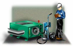
Most gearboxes are drained on a quarterly, semi-annual or annual basis - usually to eliminate contaminants. Typically, five percent or more of the old lube is left in the gearbox. If the oil is not drained shortly after shutdown, the sludge and contaminants will accumulate in the bottom of the sump and remain with the residual oil. When the gearbox is refilled with lubricant and restarted, the contaminant is re-suspended, and the oil change fails to achieve its objectives. Also, the new oil may not be clean if it is not pre-filtered.

Consider the following alternatives:

1. Drain the oil within 15 minutes of shutdown and pre-filter the new oil.

2. Instead of draining the oil, periodically filter the oil with a portable filtration cart while the machine is operating. Sample and analyze the oil periodically to determine if it needs to be changed. This strategy will reduce your overall cost of maintenance and extend the life of the gearbox, and requires little upfront investment.

3. Install full-time filtration on the gearbox and sample and analyze the oil periodically to determine if it needs to be changed. This strategy will also reduce your overall cost of maintenance and extend the life of the gearbox, but requires some upfront investment.

Alternative 1 helps, but alternatives 2 and 3 are real winners. Noria teaches the specifics of these methods in it's lubrication seminars

Viewing all 119 articles
Browse latest View live